

Electromagnetism is the branch of science that explains the relationship between electricity and magnetism. In this session, we will understand electromagnetism, magnetic fields, and magnetic field lines through simple activities.
Magnetic field:
A magnetic field is the region surrounding a magnet in which its magnetic force can be detected.
Magnetic field lines are imaginary lines used to represent the direction and strength of a magnetic field. They show the path along which a free north pole would move in the magnetic field.
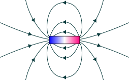
- Magnetic field lines are continuous closed curves.
- Outside a magnet, they emerge from the north pole and terminate at the south pole.
- Inside the magnet, they travel from the south pole to the north pole.
- The direction of the magnetic field at any point is the direction in which the north pole of a compass needle points.
- The magnetic field is stronger where the field lines are closer together (near the poles of the magnet).
- The magnetic field is weaker where the field lines are farther apart.
- No two magnetic field lines intersect each other, because if they did, the magnetic field would have two directions at the same point, which is impossible.
Magnetic field due to current-carrying conductors:
| Feature | Straight conductor | Circular loop | Solenoid |
| Magnetic field lines | Concentric circles around the conductor | Curved field lines; at the centre they appear almost straight and parallel | Inside: straight, parallel and equally spaced; outside: similar to a bar magnet |
| Field at centre | Not applicable | Strong magnetic field is produced at the centre | Strong and nearly uniform magnetic field is produced inside |
| Magnetic poles | No distinct north and south poles | The loop behaves like a magnet with two faces/poles | One end acts as north pole and the other as south pole |
| Current | Increase in current \(\rightarrow\) stronger field | Increase in current \(\rightarrow\) stronger field | Increase in current \(\rightarrow\) stronger field |
| Number of turns | Not applicable | More turns \(\rightarrow\) stronger field | More turns per unit length \(\rightarrow\) stronger field |
| Distance | Greater distance \(\rightarrow\) weaker field | Smaller radius \(\rightarrow\) stronger field at the centre; larger radius \(\rightarrow\) weaker field at the centre | Field inside is nearly uniform for a long solenoid |
| Core material | Not applicable | Not applicable | Soft iron core \(\rightarrow\) much stronger field |
| Direction of current | Determines field direction | Determines field direction | Determines field direction |
| Diagram |
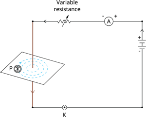 Straight conductor
|
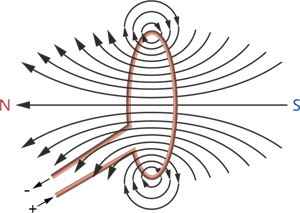 Circular loop
|
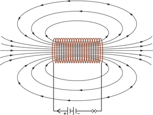 Solenoid
|
Key relationships:
| Type | Relation |
| Straight conductor | \(B\ \propto\ I\) and \(B\ \propto\ \frac{1}{d}\) |
| Circular loop | \(B\ \propto\ I\), \(B\ \propto\ \frac{1}{r}\) and \(B\ \propto\ n\) |
| Solenoid | \(B\ \propto\ nI\), where n is the number of turns per unit length |
Right-Hand Thumb Rule:
If the conductor is held in the right hand with the thumb pointing in the direction of the current, the curled fingers indicate the direction of the magnetic field lines around the conductor.
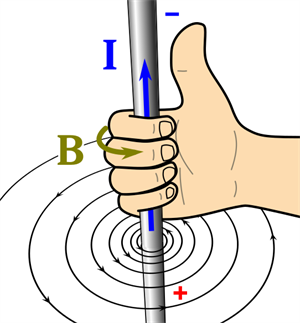
Right-Hand Thumb Rule
Fleming's Left Hand Rule:
According to Fleming’s Left-Hand Rule, stretch the thumb, forefinger and middle finger of the left hand mutually perpendicular. If the forefinger points in the direction of the magnetic field and the middle finger points in the direction of current, then the thumb gives the direction of force or motion of the conductor.
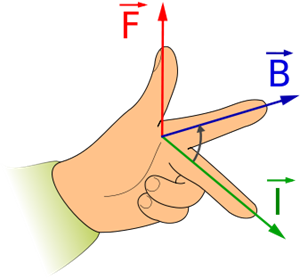
Fleming's Left Hand Rule
Domestic electric circuits:
Electric power is supplied to our homes through the mains supply using three wires: live or positive wire (red insulation), neutral or negative wire (black insulation) and earth wire (green insulation).
The live wire carries current to appliances, while the neutral wire returns current to the source. The potential difference between them is \(220\ V\).
High-power appliances such as geysers and air coolers use a \(15\ A\) circuit, while low-power appliances such as bulbs and fans use a \(5\ A\) circuit.
Electrical appliances are connected in parallel so that each appliance receives the same voltage and can be operated independently.
Earth wire:
The earth wire wire, which has insulation of green colour, is usually connected to a metal plate deep in the earth near the house. It is a safety wire connected to the metallic body of appliances. It provides a low-resistance path for leakage current and prevents electric shocks.
Electric fuse and safety measures:
A fuse is a safety device used to protect electrical circuits and appliances from excessive current.
Overloading occurs when the current exceeds the safe limit due to connecting too many appliances or a sudden rise in supply voltage.
Short-circuiting occurs when the live and neutral wires come into direct contact due to damaged insulation or faults. This causes a sudden increase in current. The heat produced melts the fuse wire, breaking the circuit and preventing damage.