Electricity helps us do many things in our daily life, such as lighting our homes and running electrical devices. For electricity to flow, there must be a complete path called an electric circuit. A switch is a simple device that helps us control this flow of electricity by turning a circuit ON or OFF.
 
In this activity, we will make a simple switch and observe how it works in an electric circuit. This will help us understand how electrical devices are controlled in everyday life.
Activity: To construct and test a simple switch.
 
Step 1: Collect two drawing pins, a safety pin (or a paper clip), two connecting wires, a small piece of cardboard, an electric cell, and a small lamp.
Step 2: Insert one drawing pin through the ring of the safety pin and fix it to the cardboard such that the safety pin can rotate freely.
Step 3: Fix the second drawing pin on the cardboard in a position where the free end of the safety pin can touch it when rotated.
Step 4: Connect one wire to each drawing pin to complete the simple switch.
Step 5: Now connect the electric cell, lamp, and the prepared switch in series as shown in the circuit diagram.
Step 6: Keep the safety pin away from the second drawing pin and observe the lamp.
Step 7: Rotate the safety pin so that it touches the second drawing pin and observe the lamp again.
 
Observation:
  • When the safety pin does not touch the second drawing pin, the circuit remains open and the lamp does not glow.
  • When the safety pin touches both drawing pins, the circuit is completed, current flows through the circuit, and the lamp glows.
  • The position where the lamp glows is called the ON position, and the position where the lamp does not glow is called the OFF position.
Conclusion:
  • This activity demonstrates that a switch works by completing or breaking an electric circuit.
  • When the switch is closed, current flows from the positive terminal of the cell to the negative terminal and the lamp glows.
  • When the switch is open, the flow of current stops and the lamp does not glow.
  • This shows that switches used in everyday electrical devices function on the same basic principle.
Electrical components and their symbols:
 
S.No. Electrical component Symbol
1. battery1612391280w400.png 9.svg
2. 101.svg battsym8.svg
3. bulblight1484831280w400.png bulbsym23 (1).svg
4. LEDw504.png download (9).png
5. swion33.svg switchclosesym4w351.png
6. swioff7.svg switopen43.svg
7. wire1200pxRomexcableagrw400.jpg wiresym12.svg
 
Circuit diagram
A circuit diagram is a representation of an electrical circuit in which symbols are used to show the different electrical components and their connections. 
Symbol of an electric cell: 

In the symbol of an electric cell, the longer line shows the positive terminal, while the shorter line shows the negative terminal.
 
9.svg
Positive and negative terminals of a cell
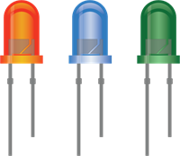
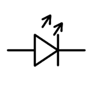
 
Symbol of an LED:

In the symbol of an LED, the triangle indicates the direction in which electric current flows, and the two arrows show that the LED emits light.
 
download (9).png
Positive and negative terminals of an LED
 
Standard electrical symbols: 

International organisations such as the International Electrotechnical Commission (IEC), the American National Standards Institute (ANSI), and the Institute of Electrical and Electronics Engineers (IEEE) develop standard symbols for electrical and electronic components. Using the same symbols worldwide makes it easier for people from different countries and fields to understand circuit diagrams clearly.